
LED Lighting control (v1) using Mosfets
LED Lighting control details
There are multiple ways how you normally can dim LED lights. The most common method is using something called PWM (Pulse Width Modulation). This will pulse the LED voltage at a certain frequency, making the LED lights go ON ~ OFF very fast in repetition. For the human eyes this will look like the LED lights are dimmed, but this does not work for a camera.
The raspberry pi camera uses a rolling shutter, meaning it scans line by line the image sensor to capture the photos. While the happens, it will actually see the LED lights switching ON ~ OFF, and this will become visible in the images by having dark and light strips of image information. There are more expensive LED power supplies in the markers that can dim LED based on current limitation, but as these are more expensive and harder to get, here a method that can be used with any kind of power supply and LED strip.
The solution described here will only allow you to have 3 settings.
- 100% LED lights
- 50% LED lights
- 0% LED lights
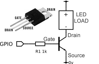
We will be able to switch ON ~ OFF each LED strip using a power mosfet. I am using IRLB8721 but you can also use a TIP120 or any other power mosfet that can handle the voltage of your LED strip.
I have 20 LED strips in my scanner, so 10 LED strips will become "group A" and the other 10 will become "group B". You will need a dedicated raspberry pi (without camera) and run this in mode 4. You can do this by setting the group.txt file to 4. This raspberry will be able to send 2 signals and ground to each mosfet board, turning ON ~ OFF each group.

To control a single LED strip with the power mosfet is fairly simple. From the GPIO signal, via an 1K resistor a connectionis made to the left pin (Gate).The - voltage of the LED strip is connected to the middle pin (drain) and the - - voltage of the LED power supply is connected to the rigth pin (source). The + voltage of the LED power supply is directly connected to the LED strip.
So how does this work. Simple, the GPIO signal now control the - voltage of the LED strips. When the signal is high the - voltage is allowed to flow between the LED strip and the LED power supply, completing the LED circuit and turning the LED ON. When the signal is low, the - voltage is not connected and therefor the LED is OFF.
In my case I created 4 boards with 5 power mosfets each as i have 4 power supplies.


I have 2 Mosfet boards with 3x group A and 2x group B. I also have 2 mosfet boards with 2x Group A and 3x Group B. So that I have equal group A and B ports!
When you have made this setup, you can now control the timing of which group should be turned on when and for how long each time a scan is made in the advanced settings in the 3D scan management software.
If you have any difficulties to get the right timing, please feel free to reach out, so I can help you configure your specific situation.